Starter motor improvement

Got the Relay, and now I've got a question:
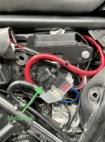
Looking at the OEM Relay, I initially see 3 Red Wires, and I believe these to correspond to what Himmie's Diagram shows to be F, B, M. Cool.
What I Don't understand is what was discussed earlier about the Ground Wire. I Totally See why the skinny little Wire that is there now would/could be inadequate, but since it 'Goes Somewhere' past the Connector, how did you solve this? I'm thinking that I could go Directly to Neg-Battery or the the Frame but with a Heavier Wire. Not sure if I should reutilize the Connector that sits in between or not...
I've gotta pick up some Heavier Gauge Wire before digging into this so I'll await an answer or two?
TIA
Bob
The OEM ground cable from the battery consists of two ground wires. One wire is for the frame ground and the other wire goes directly to one of the starter motor mounting bolts. The one that goes to the starter motor should be cut right at the terminal that is on the negative post and removed from the starter motor mounting bolt. I replaced that ground wire with a 24” long 8 gauge wire with 6mm ring terminals on each end. It is important that this ground wire runs directly from the negative battery post to the starter motor mounting bolt.
Let me know if that makes sense to you or not.
 
This is not that second answer!:p I may just Muddying the Waters, My last 443 build resulted in a Compression of only 180psi and still failed at TDC.
The 500 hesitates but does it eventually, when warm they are okay so if anything it could be, in My case that " they are still running in":ROFLMAO::ROFLMAO::ROFLMAO:
My first Bike has about 9 thousand Kms and would have had probably 9 different pistons I even replaced the Cam chain about a year ago:cautious:
Tyres are still original of course.
Some of the Bolt Heads show wear :) and quite a few have been replaced in the Cam Cover:(
and this is a Cam thread!
 
I had promise to detail my mod to the starter so here we are.

I won't give you any length detail for cables as this will depend on the routing you're going to perform and I no longer have the ABS pump, so I might have gone a shorter route.

All details about connector and parts are below.

IMG-1411.jpg
IMG-1412.jpg


This is a side to side comparison of the two complete systems, left stock right modded. As it can be seen the main power for the bike in ths stock system comes from the solenoid and it's the red encased faston on the left side. In the modded system the power to the bike comes directly from the the battery (white encased faston)

My mod is 100% reversible, meaning that no cable has been butchered during the process!

The modded system is composed by three parts: positive harness, negative harness and starter solenoid (with or without optional bypass, more on that later...)

I cannot upload all the photos in one post so keep on reading.
 
Let's start with the positive harness

IMG-1414b.jpg


Cable A1/A2 connects the solenoid to the starter, with A1 going to the starter and A2 to the solenoid. I used SCXX-Y type of connectors, where XX is the square millimeters of the cable and Y is the dimension of the hole. For this cable I used 10mm2 (AWG7) cable, as I had this one laying around, but it's a bit on the overkill side. A1 and A2 are SC10-6 lugs.

Cable B1/B2/B3 uses the same kind of wire (10mm2/AWG7). B1 goes to battery positive, B2 goes to the starter and B3 is the main power for the bike.
B2 is the same SC10-6 used in the previous cable. B1 needs to accomodate two big wires, hence I used an SC16-6 connector. B3 connector is the single pole of the connectors you find in this kit, female faston https://www.amazon.it/dp/B07Y4QFF92?psc=1&ref=ppx_yo2ov_dt_b_product_details
 
Last edited:
Negative harness is similar

IMG-1416b.jpg


Again the wire is 10mm2/AWG7 (just to be equal to positive, but again an overkill) and it's roughtly an order of magnitude larger of the stock in terms of square millimeters!

C1 goes to the battery negative and it's again a SC16-6 lug. C2 is the main negative that goes to the harness, again you'll find the right connector in the amazon link posted above, this time is the male faston, single pole.
C3 goes to one of the fixing bolt of the starter, looking to the starter from the right hand side of the bike, it goes on the left bolt. The lug this time is SC10-6.
 
Finally the meaty part:

IMG-1415b.jpg


The solenoid in my case has no marking for battery or motor connection so I assume they are identical. The markings you see in red show where the lugs from other harnesses shall be connected. 10mm socket needed.
This solenoid also has no apparent positive/negative connections, so you can swap the wires on CONN-1 as you wish. Yours might be different, check your instructions. CONN-1a si a SUMITOMO MT090 2 pole socket connector, and it goes straight right into the stock harness. Looking at the picture the left pin is the positive from the starter pushbutton, while the right is the one that goes to clutch/neutral/sidestand switch.
IF you connect it as is, the bike will operate normally with the side stand cutting off the engine if clutch is not pulled or bike not in neutral.

If you want to bypass the whole shennanigan, without messing up all the switches, you can add the bypass cable. CONN-1b is the mating SUMITOMO MT090 2 pole plug, but the cable on the right (negative) is diverted directy to the battery negative. So D1 goes to battery negative and the lug is SC6-6 in my case. wire gauge not overly important in this case.
The positive pin (left orange wire) goes again on the same connector used for the starter solenoid. If you're unsure to which side, it's the left position looking at the connector facing the retaining clip.
With the bypass cable, the bike will start at each push of the button, no matter if you're in gear, with the side stand etc, so be carefull if you decide to use this mod.

Hope these info would help! :)
 
I had promise to detail my mod to the starter so here we are.

I won't give you any length detail for cables as this will depend on the routing you're going to perform and I no longer have the ABS pump, so I might have gone a shorter route.

All details about connector and parts are below.

View attachment 937View attachment 938

This is a side to side comparison of the two complete systems, left stock right modded. As it can be seen the main power for the bike in ths stock system comes from the solenoid and it's the red encased faston on the left side. In the modded system the power to the bike comes directly from the the battery (white encased faston)

My mod is 100% reversible, meaning that no cable has been butchered during the process!

The modded system is composed by three parts: positive harness, negative harness and starter solenoid (with or without optional bypass, more on that later...)

I cannot upload all the photos in one post so keep on reading.
Nicely done Sasa. I didn’t hack up my wiring either so it’s also completely reversible although I don’t ever see a reason to revert back to the original wiring or starter relay but if I did I could.
 
Very clear and concise Sasa; nicely done!
I wish it had been 1 day earlier as I would have copied a bit of your approach, but I've done nearly identically anyhow, including the 10mm wire. I'm just finishing off a few details this morning, the main decision being on Where to have this new system reside as now there are options, then we'll see if it starts!
Cheers,
Bob
 
I would love to adopt this solution but it seems on amazon.in SUMITOMO MT090 are not currently available and i could not find another reasonable source online.

Currently unavailable.
We don't know when or if this item will be back in stock.
 
I would love to adopt this solution but it seems on amazon.in SUMITOMO MT090 are not currently available and i could not find another reasonable source online.
I'd say Aliexpress but that road is apparently already blocked for you guys...
 
It Started! Honestly the most difficult part of the job was the placement of the new Solenoid/Relay itself. I 'thought' that I'd figured that all out before cutting the new wiring and crimping/heat shrink tubing, but dog gone it that didn't work out and I had to redo a few of them. And I'm still not entirely thrilled with the outcome as it's too unprofessional, and 'may' cause me problems down the road due to the various bits getting jostled about. So I'll probably do it over once more, or not...
It turned over very nicely I must say, but I'll assess this more thoroughly with a few more cold starts, as I had my mind on Tappets and other stuff at the time.
Bob
Bob, Glad you got it working! It’s nice hearing the starter motor kick over so well isn’t it?
Too bad yours isn’t fitting very well. There isn’t much room to work with. I was able to zip tie mine securely to the meta tab that the original one was attached to. Are you able to do something like that?
 

Attachments

  • 06F2336A-F87E-47C1-91E8-1BC51858BB6D.jpeg
    06F2336A-F87E-47C1-91E8-1BC51858BB6D.jpeg
    1.6 MB · Views: 91
Hey Himmie.
You installation looks really good! Does it make the Side Cover protrude out? It Looks like we both have identical Relays, or close to it, so I might copy your job later on. I'm considering taking out the ABS like Sasa did, which would free up tons of space, and so will be considering my options for awhile.
I ended up taking off the forward section of the Inner Mud Guard and squeezing in up behind the ABS. It's probably ok like that but IF I ever do need to change a fuse I'll be fiddling a bit.
Bob, it is tight and if it was any thicker the panel would bulge out but luckily it doesn’t . I tried just about every orientation that I could think of and this is what worked for me.
 
IMG_20230429_224316_resized_20230429_105037501.jpg

Asking for Trouble with Battery this Small :giggle:
IMG_20230429_224303_resized_20230429_105037669.jpg

Not Heavy.

IMG_20230429_224907_resized_20230429_105036936.jpg

Not very Big. Nor Confidence inspiring'

IMG_20230429_224811_resized_20230429_105037321.jpg

So to keep it short, I have eliminated one Cable and made the other 2 about 40% bigger and as Short as possible.

IMG_20230429_232057_resized_20230429_115053760.jpg
IMG_20230429_232021_resized_20230429_115054010.jpg


Almost, done the Negative and started on the Positive, Plan is to incorporate an emergency start switch under the seat.
So as to override the safety switches:oops: and to be different;)
 
This Bike H2 my second Himma, was no problems starting until I started modifying things, but it was pretty new like under 3000kms.
Compression at present is around 240 Psi so I haven't gone back to the Dealer :giggle:
When it is running good it usually starts first about half the time, other times I am rocking it back in 5th ( or 4th ) then hitting it again:(
All is forgiven when it goes, :ROFLMAO: its a Beast after all!
 
IMG_20230430_115945.jpg
Not sexy, but good enough.
IMG_20230430_112717.jpg

IMG_20230430_112539.jpg
220mm.
But one concern, the cable ends RE uses are better than what I can buy, real heavy duty, their cable is thinner but the current situation passes through the ends!
 
View attachment 1027
Not sexy, but good enough.
View attachment 1028

View attachment 1029
220mm.
But one concern, the cable ends RE uses are better than what I can buy, real heavy duty, their cable is thinner but the current situation passes through the ends!
For the ends look into the solar panel market! They use heavy duty ends for the large low voltage high current panels!

They are the one mentioned before (SCXX-Y), you should have no problem finding them at a home depot or something similar!
 
Back
Top